рефераты конспекты курсовые дипломные лекции шпоры

- Раздел Компьютеры
- /
- INSTRUMENT LANDING SYSTEM (ILS)
Реферат Курсовая Конспект
INSTRUMENT LANDING SYSTEM (ILS)
INSTRUMENT LANDING SYSTEM (ILS) - раздел Компьютеры, Instrument Landing System (Ils) ...
INSTRUMENT LANDING SYSTEM (ILS)
Purpose
The instrument landing system (ILS) provides lateral and vertical position data neccessary to put the airplane on the runway for approach. The… The glideslope ground station transmits signals to give the airplane a descent… The localizer ground station transmits signals to give theAbbreviations and Acronyms
· ACP - audio control panel · alt - alternate · altn - alternateGeneral
The instrument landing system (ILS) has two multi-mode
receivers (MMRs) that contain the ILS function. The ILS
function in the MMRs receive inputs from these antennas:
· VOR/LOC antenna
· Localizer antenna
· Glideslope antenna.
Description
The VOR/LOC antenna and the localizer antenna send localizer signals through the localizer antenna switches to the MMRs. The localizer antenna… The multi-mode receivers send ILS deviation data to these LRUs: · DEUsCOMPONENT LOCATION
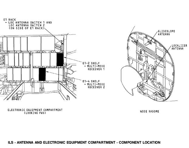
Electronic Equipment Compartment
The multi-mode receivers (MMRs) are in the electronic equipment compartment. MMR 1 is on the E1-2 shelf. MMR 2 is on the E1-4 shelf. The LOC antenna switches are on the side of the E1 rack.
Nose Radome
The glideslope and localizer antennas are in the nose radome.
The glideslope antenna is above the weather radar antenna.
The localizer antenna is below the weather radar antenna. 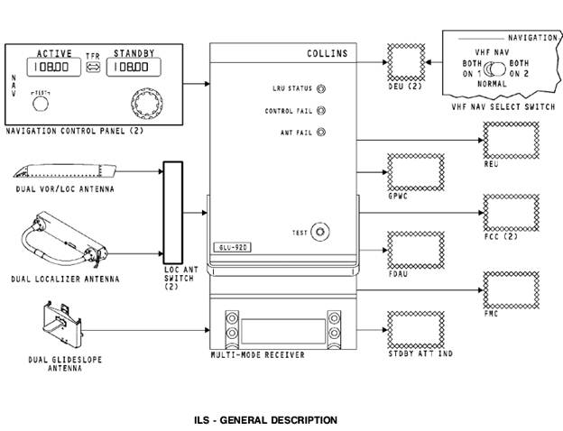
POWER INTERFACES
Power Inputs
The P18-1 circuit breaker panel also contains the NAV SENSOR DC 1 and NAV SENSOR DC 2 circuit breakers. The circuit breakers receive 28v dc from the… The P6-1 circuit breaker panel contains the NAV CONT PNL 2 and the MMR 2… When you tune an ILS frequency on the NAV control panels, 28v dc goes to the on-side FCC and LOC antenna switch. The…ILS - DIGITAL INTERFACE
General
These are the components that have a digital interface with the multi-mode receivers:
· Captain and first officer NAV control panels
· Flight data acquisition unit (FDAU)
· Standby attitude indicator
· Ground proximity warning computer (GPWC)
· Flight management computer (FMC) 1 and 2
· Display electronics units (DEU)
· FCC A and FCC B.
Digital Inputs
The NAV control panels supply frequency tune inputs to the multi-mode receivers. The NAV control panels also send tune inputs to the VOR and DME systems on a separate data bus.
Digital Outputs
The FDAU processes the data for the flight data recorder. The standby attitude indicator uses localizer and glideslope deviations for… The GPWC receives glideslope data from both ILS receivers for mode 5 (below glideslope) warnings.ILS - FREQUENCY TRANSFER AND INSTRUMENT SWITCHING
General
The frequency transfer switch on the NAV control panel and the VHF NAV transfer switch on the navigation/displays source select panel have interface with the FCCs and DEUs.
Frequency Transfer Switch
The frequency transfer switch on the NAV control panel permits the crew to transfer the frequency from the standby display window on the NAV control panel, to the active display window. The transfer switch is a momentary action switch. When you push the switch, it changes the discrete level to the FCCs. The discrete tells the FCC when there is an ILS frequency change.
Navigation/Displays Source Select Panel
The VHF NAV switch on the navigation/displays source select panel is a three position switch. The positions are; BOTH ON 1, NORMAL, and BOTH ON 2.… In the NORMAL position, MMR 1 supplies data for the captain displays and MMR 2… When you select BOTH ON 2, MMR 2 is the source for the captains displays and first officers displays.ILS - ANTENNA INTERFACE
General
The multi-mode receivers (MMRs) get RF inputs from these antennas: · VOR/LOC antenna on the vertical stabilizer · Localizer antenna in the nose radomeILS - ANALOG INTERFACES
General
The FCCs send an ILS tune inhibit to the ILS function of the MMRs during the approach (APP) mode of operation. The ILS receiver will not accept… The PSEU sends air/ground discrete signals to the MMRs to set the flight leg… The MMRs send ILS ground station audio to the REU. The REU sends the audio to the flight compartment.ILS - RECEIVER
Purpose
The multi-mode receiver contains an ILS receiver and a global positioning system (GPS) sensor unit. The ILS receiver function supplies localizer and glideslope deviation to different airplane systems. The GPS sensor unit supplies position data and time to the flight management computer system (FMCS).
Description
The MMR is a standard ARINC 600 3 MCU unit with dimensions 3.75 x 7.75 x 14.6 inches. The receiver weighs 10 pounds and uses 115v ac 400 Hz power for operation.
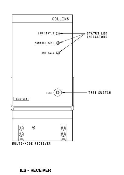
Test and Indication
There are status LED indicators and a test switch on the front of the multi mode receiver. The test switch starts a functional test of the receiver. The LED status indicators show test results.
ILS - ANTENNAS
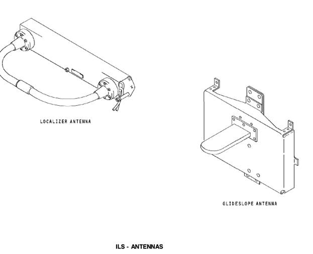
Localizer Antenna
The localizer antenna has two elements. One element supplies RF inputs to ILS receiver 1 and one element supplies RF inputs to ILS receiver 2. The localizer antenna receives frequencies from 108.1 Mhz to 111.95 Mhz at odd tenth intervals.
Glideslope Antenna
The glideslope antenna also has two elements. One element supplies RF signal inputs to MMR 1 and one element supplies RF signal inputs to MMR 2. The glideslope antenna receives frequencies from 328.6 Mhz to 335.4 Mhz.
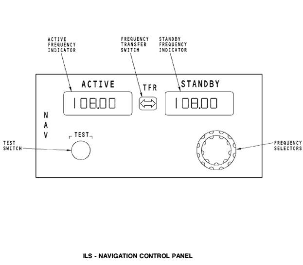
ILS - NAVIGATION CONTROL PANEL
General
The navigation (NAV) control panels supply frequency control and test signals to the DME, the MMR, and the VOR navigation radios.
Operation
The frequency transfer switch is a momentary action switch. It transfers the frequency in the standby frequency indicator to the active frequency… The frequency selectors are continuous rotary selectors. There is an inner… The NAV control panel continuous BITE function monitors the operation. The NAV control panel shows FAIL in the active…Test
When you push the NAV control panel test switch, a test command goes out on the data bus. If a VOR frequency is active, the VOR receiver starts a self test. If an ILS frequency is active, the MMR receiver starts a self test. If a DME frequency is paired with the VOR or ILS frequency, the DME interrogator starts a self test at the same time.
When you do a test of the master dim and test system, the NAV control panel shows 188.88. The display shows for two seconds on, then one second off until the test is complete.
Power Interface
The NAV control panel uses 115v ac power for operation. It also uses 28v dc for an internal monitor. The NAV control panel uses 5v ac from the master dim and test for panel lights.
ARINC 429 Interfaces
Frequency tune inputs and test commands from the NAV control panel go to the MMR on an ARINC 429 bus.
When you tune an ILS frequency, the frequency tune circuits operate switches in the NAV control panel that send these discrete signals:
· Open discrete to the REU
· Ground discrete to the DEUs
· 28v dc to the FCCs
· 28v dc to the LOC antenna switches.
Discrete Interfaces
The REU uses the open discrete to select ILS audio. The DEUs use the ground discrete to set the ILS displays. The NAV control panel sends the 28v dc… The on-side FCC supplies a discrete during an AFDS approach mode. The discrete…RF Interfaces
RF signals from the VOR/LOC antenna or localizer antenna in the nose radome, go to the localizer receiver circuits in the MMR. RF signals from the glideslope antenna in the nose radome go to the glideslope receiver circuits in the MMR.
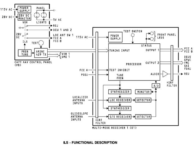
ILS - FUNCTIONAL DESCRIPTION
Receiver Functional Description
All inputs to the receiver go through a high intensity radiated frequency (HIRF) filter. This filter provides protection to internal circuits. Tune inputs from the NAV control panel go to the main processor. The processor… The receiver circuits send the RF signal inputs from theTest
To start an ILS test, push the NAV control panel test switch when there is an ILS frequency active or push the front panel test switch. When the processor receives a test signal, it does a test of operation and receiver condition. Test results show on the front panel LED status indicators. The LRU status LED shows red for test faults or green if there are no faults. The control fail LED comes on red if there is no tuning input data from the control panel. The control fail LED will show green for valid tune inputs.
ILS - CONTROLS
EFIS Controls
To show ILS data on the captain’s and F/O’s displays, set the mode selector on the EFIS control panel to the APP position.
DFCS Controls
The DEU uses the course input and ILS deviation to calculate the airplane’s deviation from the runway centerline. The DEUs compare the course input…Audio Control Panel Controls
You use the ACP receiver switches to select the ILS audio you want to listen to. The NAV 1 receiver switch selects the MMR 1 audio and the NAV 2…ILS - STANDBY ATTITUDE INDICATOR DISPLAYS
General
The standby attitude indicator gives the crew an alternate attitude indication source. The indicator also provides ILS data. You use the approach selector on the indicator to show ILS data. The approach selector has these positions:
· Off - no ILS data on indicator
· APP - ILS localizer and glideslope data shows
· B/CRS - back course ILS localizer data shows.
Indications
When the indicator receives invalid ILS data, the localizer or glideslope deviation bars go out of view and the glideslope flag or localizer flag… When the ILS data is no computed data (NCD) for localizer or glideslope data,…General
To show ILS displays on the ADI you must tune a valid ILS frequency on the NAV control panel and select it to the active display window.
Normal Display
The localizer scale can show the standard display or the expanded scale. A two-dot expanded scale can replace the four-dot scale. For the expanded… The expanded scale shows for these conditions: · LOC deviation is less than 5/8 dotRising Runway
The rising runway shows when there is a LOC signal capture and the radio altitude is below 2500 feet. The symbol goes out of view above 2500 feet.… The rising runway symbol represents the radio altitude above the runway. It…NCD Display
When the ILS data goes to an NCD condition, the CDS shows the localizer and glideslope scales and removes the pointers.
Fail Display
The amber LOC flag replaces the localizer deviation pointer
and scale when the localizer receiver function has a failure. The
amber G/S flag replaces the glideslope deviation pointer and
scale when the glideslope receiver function has a failure. 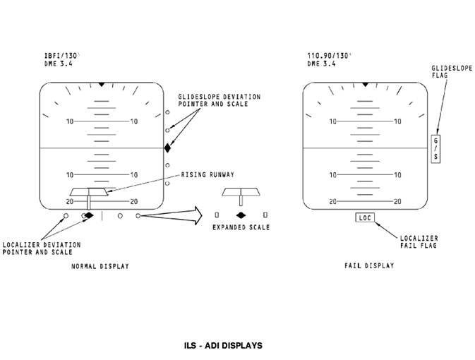
ILS - EXPANDED ILS DISPLAY
General
To show ILS displays on the CDS, set the EFIS control panel mode selector to the APP position. You must also tune a valid ILS frequency on the NAV control panel.
Normal Display
The glideslope scale is the standard four dot scale where each dot equals 0.35 degrees of deviation. The glideslope deviation pointer gives fly-to… The localizer deviation indicator and scale shows at the bottom of the NAV… The deviation scale is the standard four dot scale. One dot is equal to 1 degree of deviation. The localizer deviation…NCD Display
When the ILS data goes to an NCD condition, the CDS shows the localizer and glideslope scales and removes the pointers.
Fail Display
For invalid ILS data, the CDS replaces the localizer deviation
scale and indicator with the amber LOC flag when the localizer
receiver fails. The amber G/S flag replaces the glideslope
deviation scale and pointer when the glideslope receiver fails. 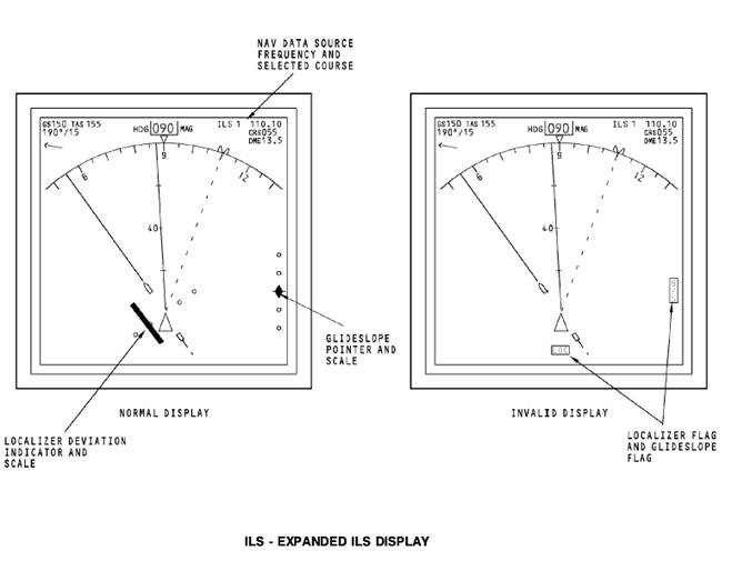
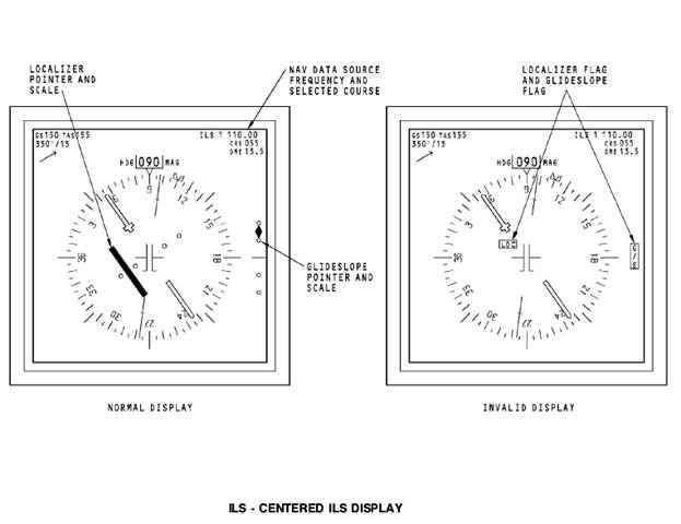
ILS - CENTERED ILS DISPLAY
General
To show the centered ILS NAV display, push the CTR switch on the EFIS control panel mode selector switch.
Normal Displays
The glideslope scale is the standard four dot scale. Each dot equals 0.35 degrees of deviation. The pointer gives fly-to commands to intercept the… The course pointer points to the number that you set on the DFCS MCP. For ILS,… The localizer deviation indicator and scale show in the center of the HSI compass card. The localizer deviation…NCD Display
For an ILS NCD condition, the CDS displays the localizer and glideslope scales and removes the deviation bar and glideslope pointer.
Fail Display
For invalid ILS data, the CDS replaces the localizer scale and deviation indicator with the amber LOC flag when the localizer receiver fails. The amber G/S flag replaces the glideslope scale and pointer when the glideslope receiver fails.
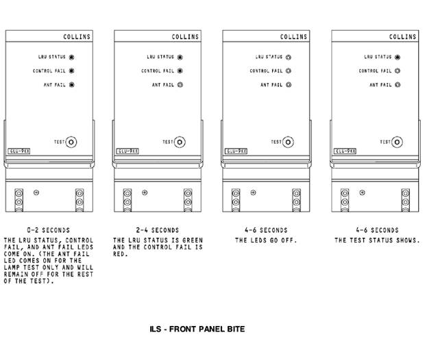
Test
When you push the test switch, the MMR does a check of the internal operation and its interface with other airplane systems. The test takes approximately 36 seconds. This is the test sequence that shows on the LED status indicators during the test:
· 0 to 2 seconds - the LRU STATUS, the CONTROL FAIL, and the ANT FAIL LEDs come on red
· 2 to 4 seconds - the LRU STATUS LED is green and theCONTROL FAIL LED is red
· 4 to 6 seconds - all LEDs go off
· 6 to 36 seconds - test status shows.
The LRU STATUS segment shows red when there is an internal failure in the MMR. Green shows that the MMR is operating normally.
The CONTROL FAIL segment shows red when an interface to the MMR has a failure. Green shows that all the interfaces to the MMR are normal.
NOTE: The ANT FAIL LED is not used at this time.
ILS - SELF-TEST
Test
You use the NAV control panels to do an ILS test from the flight compartment. The captain NAV control panel does a test of MMR 1 and the first officer NAV control panel does a test of MMR 2.
You need to set these controls to do an ILS test:
· Enter a valid ILS frequency into the active frequency display window on the NAV control panel
· Set a course on the DFCS mode control panel that is within
Degrees of the airplane heading
To see the ILS test on the NAV display, you must select the approach (APP) mode on the EFIS control panel mode selector. This is the display… · For the first 3 seconds, one dot left of localizer deviation and one dot up… · For the next 3 seconds, one dot right of localizer deviation and one dot down of glideslope deviation– Конец работы –
Используемые теги: instrument, landing, system, ils0.071
Если Вам нужно дополнительный материал на эту тему, или Вы не нашли то, что искали, рекомендуем воспользоваться поиском по нашей базе работ: INSTRUMENT LANDING SYSTEM (ILS)
Что будем делать с полученным материалом:
Если этот материал оказался полезным для Вас, Вы можете сохранить его на свою страничку в социальных сетях:
| Твитнуть |
Хотите получать на электронную почту самые свежие новости?

Подпишитесь на Нашу рассылку
Реклама


Информация в виде рефератов, конспектов, лекций, курсовых и дипломных работ имеют своего автора, которому принадлежат права. Поэтому, прежде чем использовать какую либо информацию с этого сайта, убедитесь, что этим Вы не нарушаете чье либо право.
© copyright 1999 - 2024 allRefs.net. Все права защищены. Страница сгенерирована за: 0.144 сек.
Новости и инфо для студентов