рефераты конспекты курсовые дипломные лекции шпоры

- Раздел Информатика
- /
- VHF OMNIDIRECTIONAL RANGING (VOR) SYSTEM
Реферат Курсовая Конспект
VHF OMNIDIRECTIONAL RANGING (VOR) SYSTEM
VHF OMNIDIRECTIONAL RANGING (VOR) SYSTEM - раздел Информатика, Vhf Omnidirectional Ranging (Vor) System...
VHF OMNIDIRECTIONAL RANGING (VOR) SYSTEM
Purpose
The VHF omnidirectional ranging (VOR) system is a navigation aid that gives magnetic bearing data from a VOR ground station to the airplane.
The VOR ground stations transmit signals that give magnetic radial information from 000 degrees to 359 degrees. All VOR stations reference the 000 degree to magnetic north.
Abbreviations and Acronyms
· DEU - display electronic unit · DFCS - digital flight control system · DME - distance measurement equipmentGENERAL DESCRIPTION
General
The VOR system has two VOR/marker beacon (VOR/MB) receivers. The receivers have VOR and marker beacon functions. This section covers only the VOR operation of the VOR/MB receivers.
Description
RF signals from the VOR/LOC antenna go through power dividers, then to the VOR/MB receivers. The VOR/MB receivers use the RF signals to calculate… The receivers send VOR bearing data to the display electronic units (DEU) for… The receivers send station audio and morse code station identifier signals to the remote electronic unit (REU).VOR SYSTEM - FLIGHT COMPARTMENT COMPONENT LOCATION
General
· Captain’s primary and secondary EFIS displays · Left and right EFIS control panels · First officer’s primary and secondary EFIS displaysGeneral
The VOR/LOC antenna is at the top of the vertical stabilizer. VOR/MB receiver 1 is on the E1-2 shelf and VOR/MB receiver 2 is on the E1-4 shelf.

VOR SYSTEM - POWER AND ANALOG INTERFACE
General
These are the components that have power and analog interface with the VOR system:
· Circuit breakers
· VOR antenna
· Navigation control panels
· Card files
· Remote electronics unit.
Circuit breakers
The NAV control panel circuit breakers supply 115v ac for control panel operation. The captain control panel gets power from the ac standby bus and… The NAV control panels receive 28v dc for control panel monitor operation and…VOR/ILS Antenna
The VOR/ILS antenna sends RF signals through the RF power divider 1 and RF power divider 2, to the VOR/MB receivers.
PSEU
The VOR/MB receivers get air/ground inputs from the proximity switch electronics unit (PSEU). The receiver uses the inputs to set the flight leg count for internal memory, and also inhibit test in the air.
REU
The remote electronics unit (REU) receives morse code station identifier signals and station audio from the VOR/MB receivers and supplies them to the flight interphone speakers and headsets.

VOR SYSTEM - DIGITAL INTERFACE
General
All digital interfaces are on ARINC 429 data buses. These are the components that have digital interface with the VOR/MB receivers:
· Captain and first officer NAV control panel
· Flight data acquisition unit (FDAU)
· Radio magnetic indicator (RMI)
· Flight management computers (FMC 1, FMC 2)
· Flight control computer (FCC) A
· FCC B
· Display electronics unit (DEU) 1
· DEU 2.
NAV Control Panel
The captain and first officer NAV control panels send manual tune and test command inputs to the VOR/MB receivers. The NAV control panels send tune inputs and test commands out on two data buses. One data bus goes to the multi mode receivers (MMR) and one data bus goes to both the VOR receiver and the DME interrogators.
VOR/MB Output
· FDAU for data to record by the digital flight data recorder · RMI for bearing pointer displays · FMC for position update calculationsVOR SYSTEM - VOR/MB RECEIVER
General
The VOR/marker beacon (VOR/MB) receiver contains the VOR receiver function and the marker beacon function. The VOR/MB receiver supplies magnetic bearing data from a VOR ground station.
Description
The VOR/MB receiver ia a standard ARINC 3 MCU unit with dimensions approximately 3.74”x 7.87”x 14.76”. The receiver weighs 9 pounds and uses 115v ac 400 Hz power for operation.
Test and Indication
VOR SYSTEM - VOR/MB RECEIVER
General
The VOR/LOC antenna is on the top of the vertical stabilizer. The VOR antenna receives RF signals in the frequency range of 108 MHz to 117.95 MHz. The antenna receives VOR and localizer frequencies. The VOR/LOC antenna sends VOR signals to both VOR/MB receivers.

NAVIGATION CONTROL PANEL
General
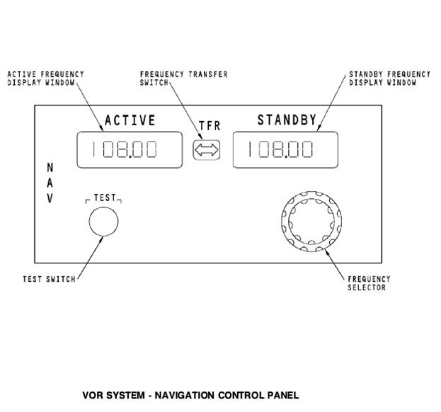
The navigation (NAV) control panel supplies frequency inputs and test commands to the DME, ILS, and VOR navigation radios.
Operation
The transfer switch is a momentary action switch that transfers the frequency in the standby frequency display window to the active frequency… The frequency select control is a continuous rotary knob. There is an inner… At power up, the frequency displays show the last frequency entry before power down.Test
When you push the NAV control panel test switch, a test command goes out to the VOR/MB receiver, ILS receiver, and DME interrogator. If a VOR frequency shows in the active frequency window, the test command goes to only the VOR/MB receiver. IF an ILS frequency shows in the active frequency window, the control panel sends a test command to only the ILS receiver. If there is a DME frequency that is paired with the VOR or ILS frequency, a test command also goes to the DME interrogators.
When you do a test of the master dim and test system, the NAV control panel shows 188.88. The display shows for two seconds on then one second off until the test is complete.
VOR SYSTEM - FUNCTIONAL DESCRIPTION
General
The receiver contains VOR and marker beacon functions. This section only covers the VOR function.
Operation
The control panel sends a discrete to the REU when you tune a VOR frequency. The REU uses the discrete to select VOR audio inputs. When you tune a VOR frequency, the control panel also sends a discrete to the… The processor sends fault data to the memory card. Only shop personnel can read the memory card contents.Test
When you push the test switch on the NAV control panel, a test command goes to the receiver when a VOR frequency is the active frequency. When the processor receives a test command, it monitors the VOR/MB receiver operation and control input status. Test results show on the status LEDs when you do a test from the front panel switches.

VOR SYSTEM - FREQUENCY TRANSFER AND INSTRUMENT SWITCHING
Frequency Transfer Switch
The frequency transfer switch on the NAV control panel transfers the frequency in the standby window display, to the active window display.
The transfer switch also provides a discrete to the FCCs. The FCCs use the discrete to disengage the autopilot when the autopilot system is in the VOR mode and the crew changes the VOR frequency.
Instrument Switching Module
With the switch in the both on 1 position, the DEU’s use VOR data from VOR/MB receiver 1 for display. With the switch in the both on 2 position the… The instrument switching module also sends discretes to the FCC when you move… EVOR SYSTEM - CONTROLS
FIS Controls
To show VOR displays on the captain’s and F/O’s secondary EFIS display, set the mode selector on the EFIS control panel to the VOR position.
VOR data shows when the mode selector is in the VOR position and a valid VOR frequency is active on the NAV control panels.
The VOR/ADF switches make the NAV display bearing pointers show either VOR or ADF station bearing. In the OFF position, the bearing pointers go out of view.
DFCS Controls
The digital flight control system (DFCS) mode control panel (MCP) supplies course data to the display electronics unit (DEU) for VOR displays. You use the DFCS MCP course select control to enter a course for the VOR station.
The DEU uses the course input and VOR bearing data from the VOR/MB receiver to calculate the airplane deviation from the VOR course.
Audio Control Panel Controls
You use the ACP volume control switches to select the VOR/MB system you want to listen to. The NAV 1 volume control selects the VOR/MB receiver 1… The voice/range selector permits you to listen to only voice audio in the…VOR SYSTEM - RADIO MAGNETIC INDICATOR DISPLAYS
General
The RMI has two bearing pointers. There is a fail flag for bearing pointer 1, and a fail flag for bearing pointer 2. The bearing pointer 1 and flag… Set the bearing pointer VOR/ADF selectors to VOR to show VOR bearing on… With the VOR/ADF selectors in the VOR position, the fail flags show for invalid data from the VOR/MB receivers.VOR SYSTEM - EFIS NORMAL DISPLAYS
General
VOR data shows on the captain and first officer displays. To show VOR displays, you must select the VOR mode on the EFIS control panels and enter a valid VOR frequency on the NAV control panels.
Bearing Pointers
The DEUs remove the bearing pointers when the VOR bearing from the VOR/MB receivers is NCD. The DEUs also remove the bearing pointers when you set… The NAV data source shows in green at the bottom left and right corners of the…Deviation Bar and Scale
The VOR deviation bar shows in magenta. The DEUs use VOR bearing from the VOR/MB receivers and course inputs from the DFCS mode control panel to calculate VOR deviation. The scale is the standard four dot scale. One dot equals five degrees of deviation.
The DEUs remove the deviation bar for NCD deviation inputs from the VOR/MB receivers.
Selected Course Pointer
The course select control on the DFCS mode control panel sets the position of the selected course pointer.
TO/FROM Pointer and Indicator
The TO/FROM indicator shows at the bottom right corner of both the centered and expanded VOR displays. The DEUs use VOR bearing from the VOR/MB… The TO indication shows when you enter a course on the DFCS MCP that takes you… The DEUs remove the TO/FROM pointer and indicators for NCD and invalid displays.NAV Data Source
The DEUs show the source of the data for the ND display in the upper right corner. The normal source for the captain NAV display is the VOR/MB receiver 1 and the normal source for the first officer is the VOR/MB receiver 2.
VOR Frequency
The DEUs change the VOR frequency to dashes for NCD inputs from the VOR/MB receivers.VOR SYSTEM - EFIS INVALID DISPLAYS
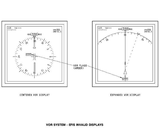
Invalid Display
The DEUs remove these displays for invalid VOR/MB receiver inputs:
· Deviation bar and scale
· TO/FROM pointer and indicator
· VOR frequency
· NAV data source
· Bearing pointers.
The DEUs show the amber VOR flags on both the centered and expanded VOR displays for VOR/MB receiver failures.
VOR SYSTEM - FRONT PANEL BITE
Test
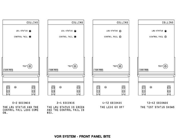
Push the test switch on the front panel to start a test of the VOR receiver. The test results show on the LED status indicators. There are two status LEDs. The LRU status LED can be red or green. The control fail LED is only red.
When you push the test switch, the receiver does a check of the internal receiver operation and its interface with the NAV control panel. The test takes 48 seconds. This is the test sequence that shows on the LED status indicators during the test:
· 0 to 2 seconds - the LRU status and the control fail LEDs are red
· 2 to 4 seconds - the LRU status LED is green and the control fail LED is red
· 4 to 12 seconds - the LRU status and the control fail LEDs go off
· 12 to 42 seconds - test status shows.
The LRU status LED indicator shows green for an LRU test pass condition or red for an LRU test fail condition. The control fail LED shows red if there is no tuning input from the NAV control panel or if the signal is invalid.
 Test
Test
You can do a test of the VOR/MB receivers from the flight compartment with the NAV control panels. The captain’s NAV control panel does a test of VOR/MB receiver 1 and the first officer’s NAV control panel does a test of VOR/MB receiver 2. You need to set these controls to do a test of the VOR/MB receivers:
· Enter a valid VOR frequency into the active frequency display window on the NAV control panel
· Set a selected course of 000 on the DFCS mode control panel
· Set the mode selector on the EFIS control panel to the VOR position
· Push the test switch on the NAV control panel.
This is the flight compartment display sequence that shows during the VOR test:
· Invalid display (VOR flag)
· NCD display (deviation bar out of view)
· Test display (deviation bar centered).


– Конец работы –
Используемые теги: vhf, omnidirectional, ranging, vor, system0.083
Если Вам нужно дополнительный материал на эту тему, или Вы не нашли то, что искали, рекомендуем воспользоваться поиском по нашей базе работ: VHF OMNIDIRECTIONAL RANGING (VOR) SYSTEM
Что будем делать с полученным материалом:
Если этот материал оказался полезным для Вас, Вы можете сохранить его на свою страничку в социальных сетях:
| Твитнуть |
Хотите получать на электронную почту самые свежие новости?

Подпишитесь на Нашу рассылку
Реклама


Информация в виде рефератов, конспектов, лекций, курсовых и дипломных работ имеют своего автора, которому принадлежат права. Поэтому, прежде чем использовать какую либо информацию с этого сайта, убедитесь, что этим Вы не нарушаете чье либо право.
© copyright 1999 - 2024 allRefs.net. Все права защищены. Страница сгенерирована за: 0.153 сек.
Новости и инфо для студентов