AIR TRAFFIC CONTROL SYSTEM
AIR TRAFFIC CONTROL SYSTEM
General
The ATC transponder also replies to mode S interrogations from the traffic alert and collision avoidance systems (TCAS) of other airplanes or ground… When a ground station or a TCAS computer from another airplane interrogates… · Maximum airspeedAbbreviations and Acronymns
· abv - above · ADIRS - air data inertial reference system · ADIRU - air data inertial reference unitGeneral Description
· Top antenna · Bottom antenna · ATC coaxial switch (2)ATC SYSTEM - COMPONENT LOCATION
Flight Compartment
The ATC/TCAS control panel is on the P8 aft electronics panel.
Electronic Equipment Compartment
These are the ATC transponder system components in the electronic equipment compartment:
· ATC transponder 1
· ATC transponder 2
· Program switch module (2)
· Top ATC coax switch
· Bottom ATC coax switch.
ATC Antenna Location
The ATC antennas are on the forward fuselage near the centerline. The top ATC antenna is at STA 430.25. The bottom ATC antenna is at STA 355.

ATC SYSTEM - ANTENNA INTERFACE
General
ATC SYSTEM - POWER, IDENTITY, CONTROL, AND AIR DATA INTERFACES
Power
ATC 1 transponder 1 gets 115v ac power from transfer (xfr) bus
1. ATC transponder 2 gets 115v ac power from xfr bus 2. The ATC/TCAS control panel gets 115v ac power from both xfr bus 1 and xfr bus 2.
Standby/On Discrete
The ATC/TCAS control panel sends a ground standby discrete to the transponder that is not in use.
Identity Code
The flight crew sets the four digit identity code and it shows on the ATC/TCAS control panel. Both transponders get the identity code from the ATC/TCAS control panel.
Control Data
The ATC/TCAS control panel also sends control data to the transponders. This control data does these functions:
· Permits mode C and mode S operation.
· Lets the transponder send the special position identification (SPI) pulse or airplane identification code.
Air Data
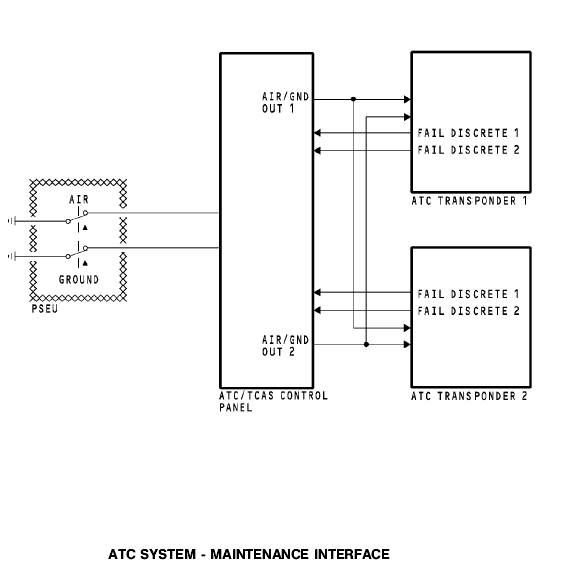
ATC transponder 1 gets air data at AD input 1 from the left ADIRU air data reference (ADR) bus 4. The left ADIRU also supplies air data to the ATC 2…ATC SYSTEM - MAINTENANCE INTERFACE
PSEU
The proximity switch electronics unit (PSEU) sends air/ground discretes through the ATC/TCAS control panel to the transponders.
These are the purposes of the air/ground discretes:
· Prevent ground tests of the ATC system in the air
· Prevent mode A and mode C replies on the ground
· Defines flight legs in the non-volatile memory.
Transponder Fail Discretes
Each transponder built-in test equipment (BITE) continually monitors the equipment for failures. If the BITE detects a failure, the transponder sends the fail discretes to the ATC/TCAS control panel.
ATC SYSTEM - TCAS INTERFACE AND PROGRAM PINS
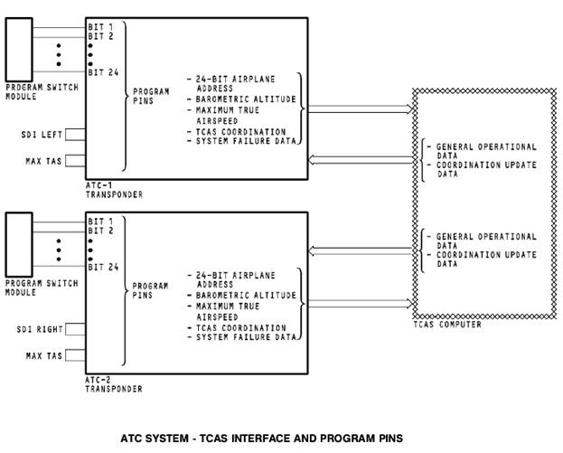
Program Pins
· Airplane mode S address · Source destination identifier (SDI) · Maximum true airspeed.Digital Data to TCAS
The active ATC transponder sends this data to the traffic alert and collision avoidance system (TCAS) computer:
· The 24-bit mode S airplane identification. TCAS needs the airplane mode S identification for maneuver coordination.
· Barometric altitude
· Maximum true airspeed
· TCAS coordination message data
· ATC transponder system failure data.
TCAS to Active Transponder
The TCAS computer sends this data to the active transponder:
· General TCAS operational data
· Coordination update data.
ATC SYSTEM - SUPPRESSION INTERFACE
General
ATC SYSTEM - ATC TRANSPONDER
General
The ATC ground station interrogates the ATC transponder with a pulse-coded signal at a frequency of 1030 MHz.
The transponder responds with pulse-coded signals at a frequency of 1090 MHz.
Characteristics
The transponder responds to air traffic control radar beacon system (ATCRBS) mode A and mode C interrogations. The transponder also responds to air traffic control and the TCAS computer with the mode select (mode S) format.
The ATC transponder has a non-volatile flight-fault memory.
Front Panel Indications
The light emitting diode (LED) status indicators on the front panel show for these conditions: · LRU STATUS (green), if there are no LRU failures · LRU STATUS (red), if there is an LRU failureATC SYSTEM - ATC ANTENNA
Purpose
The ATC L-band blade antenna receives 1030 MHZ interrogation signals from ATC ground stations and other airplanes that have TCAS. The ATC transponder transmits the reply signals through the L-band antenna.
Physical Description
The coaxial cable connector connects to the antenna. The antenna has an O-ring moisture seal and attaches to the airplane by four screws. The ATC and DME antennas are the same and are interchangeable.

ATC SYSTEM - ATC COAX SWITCH
General
These are the electrical connector inputs: · ATC antenna switch circuit breaker · ATC/TCAS control panel.ATC SYSTEM - TRANSPONDER RECEIVE FUNCTION
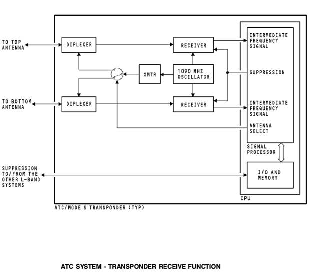
General
The antennas send the interrogation signals to the transponder.
The signals go through the diplexer circuits to two receivers. The 1030 MHz interrogation signal mixes with a 1090 MHz signal from the 1090 MHz oscillator. This makes an intermediate frequency signal that the signal processor uses.
Suppression
When the transponder gets a suppression pulse from another system, the signal processor circuits do not permit the receiver circuits to operate.
Antenna Select
The antenna select circuit chooses the diplexer and antenna that supplies the strongest receiver signal. The transmission of the reply signal goes through the selected diplexer and antenna.
Signal Processor
The signal processor determines if the transponder receives a valid interrogation signal. It also determines the correct reply mode; mode A, mode C, or mode S.
ATC SYSTEM - TRANSPONDER TRANSMIT FUNCTIONAL DESCRIPTION
Transmit
The mode A reply contains the airplane identity code. The mode C reply contains the airplane altitude. The mode S replies contain a unique 24-bit airplane address, identity code, altitude information, and TCAS…Test
When you apply power or do a test of the ATC transponder system, the built-in test equipment (BITE) does a check of the operational status of all the internal circuits and for the correct antenna impedance. The BITE circuits identify any failures and put them into the non-volatile memory.
The LEDs on the front panel of the transponder come on to report these conditions:
· Transponder status
· Antenna status
· Transponder control interface status
· Altitude interface status.
General
Push the TEST switch on the front of the transponder or select TEST on the ATC/TCAS control panel to start a self-test of the ATC system. During the test, the transponder BITE circuits do these functions:
· Normal operation test
· Memory tests
· Simulated interrogation test of the receiver circuits
· Antenna impedance test
· TCAS interface test
· Valid control and altitude inputs monitor.