MARKER BEACON SYSTEM
MARKER BEACON SYSTEM
General
The marker beacon system supplies visual and aural indications when the airplane flies over airport runway marker beacon transmitters.
Abbreviations and Acronyms
· AC - alternating current · ACP - audio control panel · ALT - alternateGENERAL DESCRIPTION
General
The marker beacon system has an antenna and a VOR/marker beacon (VOR/MB) receiver. The marker beacon function only operates in the VOR/MB receiver 1 position.
Operation
· Marker beacon audio to the remote electronics unit (REU) · Marker beacon data to the common display system (CDS) display electronics… · Marker beacon data to the flight data acquisition unit (FDAU).COMPONENT LOCATIONS
General
The marker beacon antenna is on the bottom of the fuselage. The VOR/MB receiver 1 is in the electronic equipment compartment E1-2.
The marker beacon data shows on these display units:
· Left outboard display unit
· right outboard display unit.

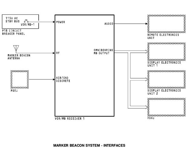
INTERFACES
Power
The VOR/marker beacon (VOR/MB) receiver 1 uses 115v ac power from the standby bus.
Antenna Interface
The marker beacon antenna sends radio frequency (RF) signals to the VOR/MB receiver 1.
PSEU
The proximity switch electronics unit (PSEU) supplies an air/ ground discrete signal to the VOR/MB receiver 1. The VOR/MB receiver uses this signal for these functions:
· Prevent a test in the air
· Count flight legs.
Audio Interface
The VOR/MB receiver 1 sends marker beacon audio to the remote electronics unit (REU). The REU supplies marker beacon audio to the flight compartment.
Marker Beacon Data
The VOR/MB receiver 1 supplies marker beacon data to the 1 and 2 common display system (CDS) display electronics units (DEU). The receiver also supplies marker beacon data to the FDAU.
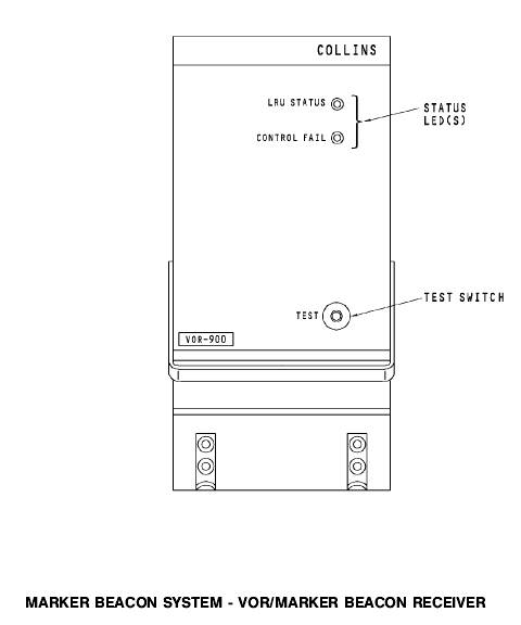
VOR/MARKER BEACON RECEIVER
General
The VOR/marker beacon (VOR/MB) receiver has these two parts:
· VOR receiver
· Marker beacon receiver.
The marker beacon system operates in the VOR/MB receiver 1 position. The marker beacon receiver receives 75 MHz signals.
Test and Indications
You do a test of the these VOR/MB receiver 1 functions at the same time:
· VOR function
· MB function.
There is a test switch and two light emitting diodes (LEDs) on the front panel of the VOR/MB receiver.
Flight Fault Memory
The VOR/MB receiver has a nonvolatile flight fault memory.
Only shop personnel can read the memory.
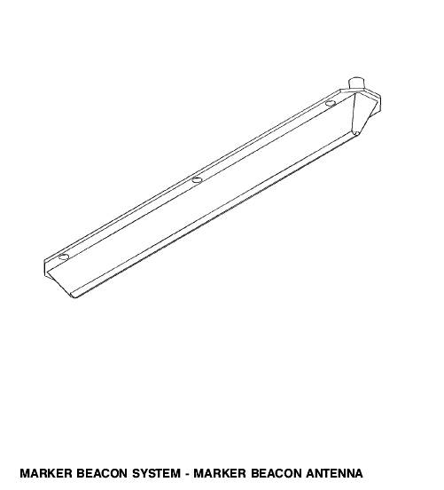
MARKER BEACON ANTENNA
General
The marker beacon antenna receives signals from marker beacon ground stations.
Six screws hold the antenna to the fuselage.
DISPLAYS AND AUDIO OUTPUTS
General
When the airplane goes above a marker beacon transmitter, marker beacon data shows on the primary flight display (PFD).
If you want to hear marker beacon audio, you select the marker beacon audio on the audio control panel (ACP).
Display Types
OM shows when the airplane goes above the outer marker. The OM letters are cyan.
MM shows when the airplane goes above the middle marker.
The MM letters are yellow.
IM shows when the airplane goes above the inner marker, backcourse marker, or an airways marker. The letters IM are white.
NCD/Fail Display
If marker beacon data fails or is no computed data (NCD), the display does not show.
Audio General
The ACP supplies control signals to the remote electronics unit (REU). The REU uses the control signals to select the audio that goes to the flight interphone speakers and headsets.
Use the ACP to listen to marker beacon audio.
Audio Operation
You make these ACP selections to listen to marker beacon audio:
· Push the marker beacon receiver volume control to make the marker beacon audio come on
· Turn the marker beacon receiver volume control to change the volume level.
Audio Outputs
· Outer marker (OM) is 400 Hz, continuous dashes (- - - -) · Middle marker (MM) is 1300 Hz, alternate dots and dashes (-.-.-.-.-) · Inner marker (IM) is 3000 Hz, continuous dots (......)FUNCTIONAL DESCRIPTION
Marker Beacon Signal
The bandpass filters are at 400 Hz, 1300 Hz, and 3000 Hz. The filters send the signals to an audio amplifier and to an input/ output (I/O) card. The… The DEU shows marker beacon data on the PFDs.Monitor and Test
During the test, a self-test frequency generator gives a 75 MHz RF signal that has 400 Hz, 1300 Hz, and 3000 Hz audio signals. The bandpass filters… The BITE circuits monitor the condition of the output data of the VOR/MB… The VOR/MB receiver gets an air/ground discrete signal from the proximity switch electronics unit (PSEU). The VOR/MB…TEST – 1
General
When you do a test of the marker beacon system, you test the VOR receiver 1 at the same time.
Operation
· 0 to 2 seconds - the LRU status and the control fail LEDs are red · 2 to 4 seconds - the LRU status LED is green and the control fail LED is… · 4 to 12 seconds - the LRU status and the control fail LEDs go offTEST – 2
General
You do a remote test of the navigation receivers with the navigation control panel. The navigation control panel does a test of these receivers:
· VOR/MB receiver
· ILS receiver.
When you do a test of the marker beacon system, you do a test of the VOR/MB receiver 1 at the same time.