рефераты конспекты курсовые дипломные лекции шпоры

- Раздел Информатика
- /
- RADIO ALTIMETER SYSTEM – INTRODUCTION
Реферат Курсовая Конспект
RADIO ALTIMETER SYSTEM – INTRODUCTION
RADIO ALTIMETER SYSTEM – INTRODUCTION - раздел Информатика, Radio Altimeter System – Introduction ...
RADIO ALTIMETER SYSTEM – INTRODUCTION
General
The flight crew and other airplane systems use the altitude data during low altitude flight, approach, and landing. The system has a range of -12 to 2500 feet. An adjustable radio minimums alert operates with the radio altitude system and is independently selectable from 0 to…Abbreviations and Acronyms
· AID - aircraft installed delay · altm - altimeter · ant - antennaRA SYSTEM - GENERAL DESCRIPTION
General
The altitude data and signal validity is sent on two ARINC 429 data buses. ARINC 429 data bus 1 sends data to these components: · Flight control computers (FCC)RA SYSTEM - COMPONENT LOCATION – 1
General
The RA receiver/transmitters are on the E3 rack in the electronic equipment (EE) compartment.
The RA antennas are on the bottom of the fuselage.

RA SYSTEM - COMPONENT LOCATION - 2
General
These are the components in the flight compartment that interface with the RA system:
· Left and right EFIS control panels
· Common display system (CDS) display units (DU).

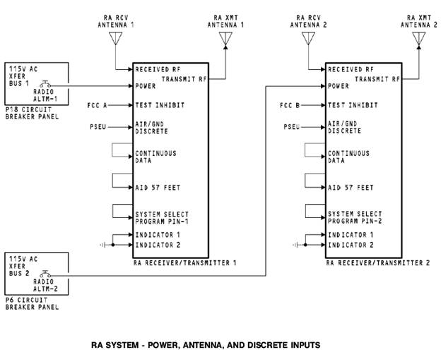
RA SYSTEM - POWER, ANTENNA, AND DISCRETE INPUTS
Power
Power for the RA receiver/transmitter 1 is 115v ac from xfer bus 1.
RA receiver/transmitter 2 receives 115v ac from xfer bus 2.
Antenna Interfaces
The transmit antenna sends radio frequency (RF) signals to the ground. The receive antenna sends reflected RF signals to the receiver circuits of the RA receiver/transmitter.
Flight Control Computer Discrete
The flight control computers (FCC) supply a test inhibit signal to the RA receiver/transmitter. This signal prevents an RA test when ILS mode is selected.
PSEU
The RA receiver/transmitter keeps internal and external faults in a nonvolatile fault memory. The RA receiver/transmitter keeps these faults by flight segments. The RA identifies the faults as airborne faults or ground faults. The proximity switch electronics unit (PSEU) gives the air/ground condition.
Input Program Pins
These are the radio altimeter program pins:
· Continuous data. When grounded, lets continuous altitude data be transmitted to user systems
· Aircraft installed delay (AID) of 57 feet. This lets the RA system compensate the altitude calculation for antenna cable length and distance of the RA system antennas from the ground at touchdown
· System select. Used to identify which system.
Indicator Discrete
The indicator discrete supplies the status of flight compartment radio altitude indicators. This system does not use radio altitude indicators.
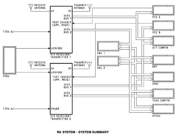
RA SYSTEM - DATA BUS OUTPUTS, DECISION HEIGHT INTERFACE
General
The RA system supplies radio altitude (RA) data to these components:
· FCC A and the FCC B
· Autothrottle computer
· Display electronics unit (DEU) 1 and the DEU 2
· Weather radar R/T
· GPWC
· FDAU
· TCAS computer.
RA Receiver/Transmitter Outputs
The autothrottle uses radio altitude in the TO/GA calculations and autothrottle flare calculations. The DEUs use radio altitude data to calculate the type of radio altitude… The weather radar R/T uses radio altitude to turn on or off the predictive windshear function and to enable/disable…EFIS Control Panel Interface
The EFIS control panels supply radio minimums values to the DEUs. The DEUs use radio minimums and radio altitude to calculate radio minimums alerts that show on the display units.

RA SYSTEM - RA RECEIVER/TRANSMITTER
Purpose
The RA receiver/transmitter calculates radio altitude.
The RA receiver/transmitter has a non-volatile memory which stores fault information from the last 63 flights. It can store up to 13 faults per flight. Only shop personnel read the non-volatile memory information.
Description
These are the operation limits of the receiver/transmitter:
· Frequency = 4235 Mhz to 4365 Mhz
· Transmit power = 500 mw nominal
· Operating range = -12 to 2500 feet.
A test connector on the front panel connects test equipment for shop tests.
Operation
· Red or green LRU STATUS LED shows the receiver/ transmitter operational status. It comes on green when the receiver/transmitter is OK. It comes on red when theRA SYSTEM - RA ANTENNA
Purpose
The RA system uses four antennas that transmit and receive RF signals. Each RA receiver/transmitter has a transmit and receive antenna. The transmit and receive antennas are the same and interchangeable.
Physical Description
Four screws attach each antenna to the bottom of the fuselage.
There is an O-ring seal in a groove around the coax connector. The O-ring seal gives moisture protection. The radiation side of the antenna has red markings “FWD” and “DO NOT PAINT”.
Training Information Point
Do not paint the radiation surface or the back plate of the antenna. Paint does not permit the antenna to send or receive RF signals.

RA SYSTEM - OPERATION - 1
EFIS Control Panel
The minimums controls have these three controls: · A two-position rotary switch (minimums reference selector) · A spring loaded rotary switch (minimums altitude selector)Display Unit
Radio altitude shows in white for airplane altitude between -12 and 2500 feet. This is when the radio altitude values update: · Two foot increments from -12 to 100 feet · Ten foot increments from 100 to 500 feetRadio Minimums Alert
When a radio minimums alert occurs, the radio altitude display changes from white to amber. Also, the radio minimums display changes from green to amber and goes off and… After three seconds, the display continues to show amber until it is set back to normal.Altitude Alert
When the airplane descends below 2500 feet, ALT shows in white on the DU above the radio altitude display. Each of these will remove the ALT display:
· The airplane climbs above 2500 feet radio altitude
· The airplane descends below 500 feet radio altitude
· The minimums reference selector is in the RADIO position and the reset switch is pushed.
Rising Runway
· Radio altitude is less than 2500 feet · ILS localizer deviation shows on the ADI. The rising runway symbol moves toward the airplane symbol on the ADI as the airplane altitude decreases from 200 feet…RA SYSTEM - OPERATION – 2
RA Data NCD
RA data NCD causes the RA display and rising runway symbol to be removed. The NCD occurs when the return RA signals are too weak or the radio altitude is more than 2500 feet. Also, the rising runway will not show when the ILS is not captured.
RA Data Invalid
Invalid RA data causes a amber RA flag to show in the radio altitude position. Invalid RA also causes the rising runway symbol to be removed. The invalid data occurs when the RA receiver/transmitter finds a failure in the RA system.
Radio Minimums Data Invalid
Invalid EFIS control panel data causes the amber displays control panel flag to show and the letters RADIO and the radio minimums value to be removed.
Also, the vertical speed indication (VSI) is grey. There is no VSI fail flag for this condition.

RA SYSTEM - RF PROCESSING
General
The radio altimeter transmits a frequency modulated/continuous wave (FM/CW) signal through the transmit antenna. This signal is a CW carrier that scans linearly from 4,235 to 4,365 MHz 145 times a second.
Transmit and Receive
· FCC A or FCC B · Autothrottle computer · DEU 1 and DEU 2Input Program Pins
The aircraft installation delay (AID) program pin is grounded to the 57 feet selection. This calibrates the system so that the radio altitude is 0… · Length of the antenna cables · Fuselage to ground distanceRA SYSTEM - FAULT DETECTION
BITE Module
The built-in test equipment (BITE) module monitors the circuits in the RA receiver/transmitter for faults. The flight fault memory stores the number of faults for each flight leg. Shop personnel use the automatic test equipment (ATE) connector to read the fault memory contents.
Test
A test switch on the front of the RA receiver/transmitter starts an RA self-test. LEDs show the results of the self-test.
The self-tests do a check of these:
· Receiver/transmitter internal status
· ARINC 429 output transmitters status
· Antennas and coaxial cables.
The flight control computers (FCCs) supply a test inhibit signal to the receiver/transmitters. This prevents an RA test when the FCC is in the approach mode. 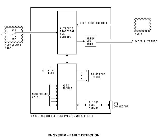
RA SYSTEM - FRONT PANEL BITE
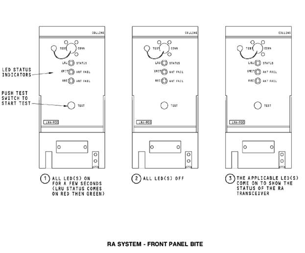
Test
The front panel BITE test only operates when the airplane is on the ground.
Momentarily push the test switch on the front of the RA receiver/transmitter to start a self test. Monitor the front panel for these results:
· Time = 0 seconds - all front panel LEDs come on red
· Time = 2 seconds - LRU STATUS LED changes to green
· Time = 4 seconds - all front panel LEDs go off
· Time = 6 seconds - applicable LEDs come on to show a normal (green) or fault (red) condition
· Time = 36 seconds - Front panel LEDs go off.
RA SYSTEM - FLIGHT COMPARTMENT BITE DISPLAY
General
The front panel BITE test causes the RA receiver/transmitter to send a test altitude to the flight compartment display units. The test altitude is 40 feet. The test altitude shows during the full test. The altitude display goes back to normal when the test is complete.

– Конец работы –
Используемые теги: Radio, altimeter, system, introduction0.069
Если Вам нужно дополнительный материал на эту тему, или Вы не нашли то, что искали, рекомендуем воспользоваться поиском по нашей базе работ: RADIO ALTIMETER SYSTEM – INTRODUCTION
Что будем делать с полученным материалом:
Если этот материал оказался полезным для Вас, Вы можете сохранить его на свою страничку в социальных сетях:
| Твитнуть |
Хотите получать на электронную почту самые свежие новости?

Подпишитесь на Нашу рассылку
Реклама


Информация в виде рефератов, конспектов, лекций, курсовых и дипломных работ имеют своего автора, которому принадлежат права. Поэтому, прежде чем использовать какую либо информацию с этого сайта, убедитесь, что этим Вы не нарушаете чье либо право.
© copyright 1999 - 2024 allRefs.net. Все права защищены. Страница сгенерирована за: 0.13 сек.
Новости и инфо для студентов